 Manual home
 Send Feedback

 Print
Print
If the correct setting cannot be reached
- In some cases, the sensor assembly X needs to be moved UP or DOWN.
- In order to have full access to the top sensor assembly the solenoid assembly must be removed.
- .Loosen the two hex screws holding the solenoid assembly.
- Loosen the hex screw W move the sensor assembly in the desired direction.
Note: Check motor leaver arm, it is not allowed for the leaver arm to reach end of stroke but make sure that the fill-nozzle is pushed down far enough!
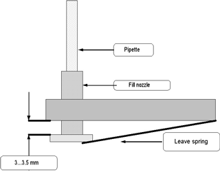
The next drawing explains where and how to measure.

Check the distance as shown in the above drawing, this is done at the pipette position.
See Also |
 Mechatronics home
 Send Feedback

 Print
Print
|
Page last reviewed: 03/05/2010 11:07:19 (Version: MRN--EN) ©2019 RR Mechatronics |