Manual home Send Feedback Print

Previous Topic

Next Topic

Book Contents

Book Index

Nozzle unit adjustment Version 1 (ESRI039205)

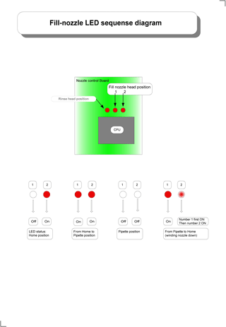
Quick check on the LED status of the four stages;

This adjustment is critical and must be performed as described. Use drawing ESRI039205 Fill Nozzle motor assembly

  1. Leave or switch the Compact ON.
  2. Bring the fill nozzle to the pipette position. See Menu selection (3) (nozzle) menu selection how to obtain the movement.
  3. When the fill nozzle is in the Pipette Position. LED's 1 and 2 are going from status A to B to C.
  4. Observe the Pipette Position status C on nozzle control board. Both LED's must be OFF.
  5. Push a small piece 2*4mm PVC tube on the shaft of the fill nozzle motor and wind fill-nozzle downwards. (See assembly drawing ESRI039205)
  6. When the fill-nozzle is engaged with the pipette and the fill-nozzle motor is wound down the LED 1 comes ON then LED 2 comes ON. See LED status D.
  7. Winding the motor shaft further will cause situation B again.
  8. Turn motor so that both LED’s are OFF, the fill-nozzle should be engaged with the pipette.
  9. Send the fill-nozzle back to home position, LED’s status is shown in situation A.

Misalignment is when fill-nozzle engaged to pipette and the LED 2 comes ON before LED 1 in situation D, this means the sensors must be readjusted.


fill_nozzle_led_sequence_small

Detailed Fill nozzle led sequence

When the sensor cannot be adjusted correctly see Help to make the correct sensor adjustment.

For adjusting the fill nozzle use the Block diagrams over adjusting the fill nozzle

Click here If the correct setting cannot be reached

See Also

Led status of the four stages

Help to make the correct sensor adjustment

Block diagrams over adjusting the fill nozzle

If the correct setting cannot be reached

To top of page Mechatronics home Send Feedback Print