 Manual home
Send Feedback
Manual home
Send Feedback
 Print
Print
|
|
|
|
|
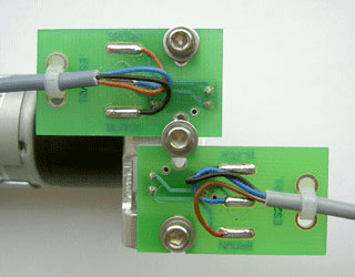
Nozzle unit adjustment Nozzle drive Version 3 (ESRI039311)
Two sensors are fitted on the bracket ESRI030250.
|
Picture 1 |
|
|
Picture 2 |
Picture 3 |
See Menu selection (nozzle) how to obtain the movement.
Check the LED status of the four stages.
Block diagrams for adjusting the fill nozzle;
3. Pipette position. The fill nozzle is engaged with the pipette. |
4. From pipette to home position. This is the movement from the pipette to the fill nozzle cap. |
|
|
Detailed Fill nozzle pipette home position |
Detailed Fill nozzle to Home position |
Detailed Fill nozzle led sequence
Return to Led status of the four stages.
See Also |
Mechatronics home
Send Feedback
Print
|
Page last reviewed: 08/04/2015 13:34:36 (Version: MRN--EN) ©2019 RR Mechatronics |