 Manual home
Send Feedback
Manual home
Send Feedback
 Print
Print
|
|
|
|
|
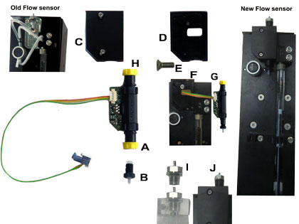
Replacement of the EDTA electronic diluent flow sensor
A new type of diluent flow sensor is introduced in 2015. This new type is an electronic flow sensor. (ESRI060954).
The best and the quickest way to do the modification is to remove the diluter from the ESR unit.
- Close the Starrsed software
- Switch off the ESR unit
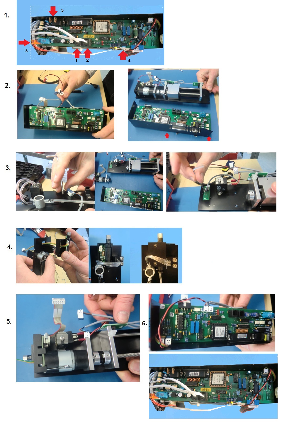
1. Remove diluter unit
- Close the supply to the diluter with a clamp (saves diluent and time on priming diluent)
- Remove the tube to the Y-piece (T-Piece is applicable)
- Remove the supply tube which is connected to the pinch valve
- Disconnect the two IIC communication lines (1,2) and the power connector (3).
- Disconnect the white flex print (4) to the Diluter start sensor, be careful with the cable clamp on this small connector
- Disconnect the earth connection (5)
- Loosen the mounting screws and remove diluter unit from the instrument
2. Disassemble diluter unit:
- Place the diluter unit on a table
- Remove the diluent flow sensor housing with the ball bearing (this could be fitted very tight)
- Disconnect all the connectors from the PCB
- Remove the black cover by removing the two M3 screws
- Remove the PCB from the plastic studs
Put the PCB aside. - Remove now the two screws from the bracket which is holding the diluter motor
Put the motor aside
Remove the sensor from the black plate, handle the syringe with care
3. Open the housing of the diluent flow sensor
- Remove the two screws
- Remove the top cover from the sensor
4. Mounting new flow sensor
- Lead the connection cable through the hole.
- Place the bottom half of the cover onto the diluter plate.
- Fix the cover with the delivered screw.
- Push the printed circuit board into the bottom half of the cover.
- Place the top cover and carefully fix this cover with the two screws.
5. Assembling diluter unit
- Mount the diluter motor back on the base plate
- Replace the PCB on the plastic studs
- Fix the black cover onto the bracket with the two M3 screws.
- Reconnect all the connectors onto the board
- Check the potmeter of the EDTA Flow sensor is turned CW till you hear clicking sound comes from the potmeter. (Turn from the syringe to the 25 pins connector.)
- Measure there is 10 volt and more measured on the wires Yellow and Orange.
Note: Remove the white cover from the connector and put your pins on the outside of the connector. The voltage must be >10 volt.
6. Re-installation diluter unit
- Re-install the diluter in the ESR unit
- Reconnect the flex print cable, be careful with the cable clamp on this small connector
- Reconnect the two IIC cables
- Reconnect the power cable
- Reconnect the earth connection cable
- Reconnect all the tubing on the new diluent flow sensor
- Reconnect the tube from the Y-piece to the dilution flow sensor
- The last connection to be done is the supply line, remove the clamp.
7. Final step
- Switch on the ESR unit
- Restart the Starrsed software
- Go to maintenance tab and start prime diluent
If dilution flow detection alarm will come up, switch Diluent flow check OFF (Settings-> Diluter settings). - Test the new Dilution flow sensor with Maintenance –> Check sensors - > Check Diluent Flow sensor
- Check if Diluter flow check is switched ON (Settings-> Diluter settings).
See Also |
Mechatronics home
Send Feedback
Print
|
Page last reviewed: 16/07/2019 14:39:41 (Version: MRN--EN) ©2019 RR Mechatronics |