 Manual home
Send Feedback
Manual home
Send Feedback
 Print
Print
|
|
|
|
|
Liquid Flow and Vacuum
In order to aspirate, rinse and dry, the ESR unit uses vacuum. The main vacuum pump can be found at the bottom of the cabinet, remove the protection cover to gain access to the main vacuum pump.
NOTE: Disconnect the mains cable before working on the pump!
The vacuum pump is an oil-free rocking piston pump and can be operated at 230v or 115v 50/60Hz.
Peristaltic pumps are used for pumping the rinse, diluent (as used for cleaning) and waste.
The vacuum flow is monitored with the vacuum flow sensor. The flow sensor constantly measures the flow in the system during the aspiration. The software calculates the speed of the diluter syringe.
Before aspiration, the fill block is connected to the pipette and the stability of the vacuum flow is tested. At first the absolute numbers (with sample valve open) and then the leakage numbers (with sample valve closed) When the flow numbers are not stable, the system will abort aspiration and the carousel moves to the next pipette. In the error log the message Air flow failure (E9) is shown, including pipette number.
The liquid waste pump can be found at the left, behind the waste container and cyclone. This is a membrane type pump and is capable of emptying the cyclone while it is under vacuum. Make sure that the inlet/outlet tubes are not kinked; this will cause a separator error.
The cyclone is situated behind the waste container. The cyclone (liquid separator) must be cleaned frequently. The float must move freely and prevents excessive foam entering the HEPA filter, which can be found on top of the cyclone. Bacterial HEPA filter QWLV040002 must be replaced regularly, see Level 4 maintenance.
All the waste and air flows through the manifold ESRI 010910 (See Drawing ESRI070917 Vacuum tube assembly) and is finally collected in the cyclone. The air escapes through the vacuum pump and exhaust muffler in the vacuum pump compartment.
The manifold ESRI010910 is susceptible for blockages, make sure that the system is flushed sufficiently according the maintenance procedures.
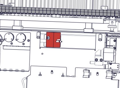
Manifold location under the steel plate.
In This Chapter |
Mechatronics home
Send Feedback
Print
|
Page last reviewed: 30/03/2018 08:49:18 (Version: MRN--EN) ©2019 RR Mechatronics |