 Manual home
Send Feedback
Manual home
Send Feedback
 Print
Print
|
|
|
|
|
WI-234 Level 3 maintenance
Work instruction Number 234 |
|
Page 1 of 1 |
Purpose: Maintenance level 3 |
Safety: Bio Hazard area |
|
Instrument: Starrsed TL |
Revision: 003, 2021 |
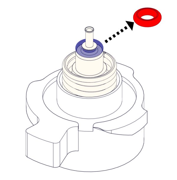
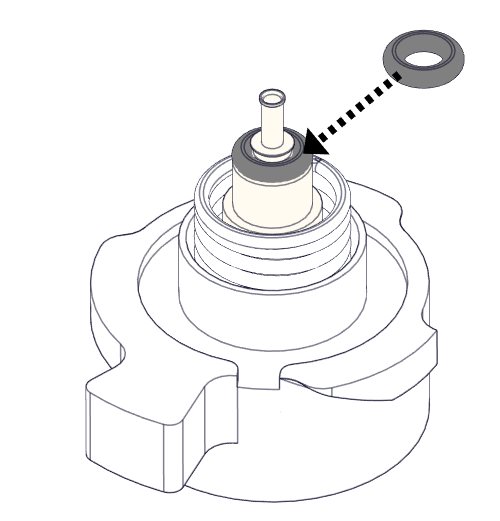
- Clean fill nozzle and exchange O-ring Fill Nozzle
- Clean waste separator
- Exchange peristaltic pump tubes
- Fill & Clean
- Replace Needle O-ring (if applicable)
- Check/Clean liquid sensor
- Sensor check
- Exchange waste pump tube
- Exchange pinch valve
- Final cleaning and preparation
- Air filter replacement
Inactivate the instrument in the LAS.
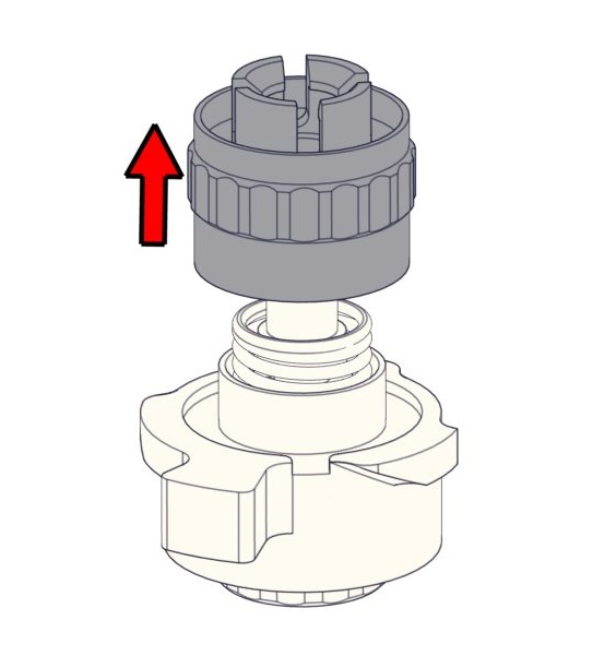
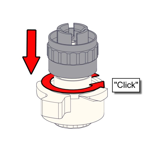
Clean fill nozzle and exchange O-ring Fill Nozzle
1. |
|
2. |
|
3. |
|
4. |
|
5. |
|
6. Clean fill nozzle The use of a toothbrush and detergent is recommended.
|
||||
7. |
|
8. |
|
9. |
|
|||
10. |
|
11. |
|
12. |
|
|||
13. |
|
|
|
|
|
|||
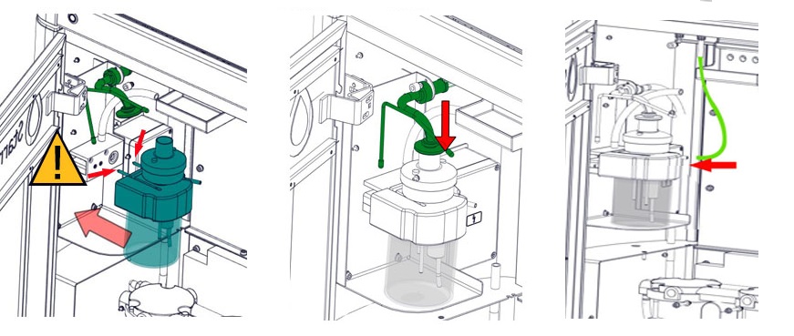
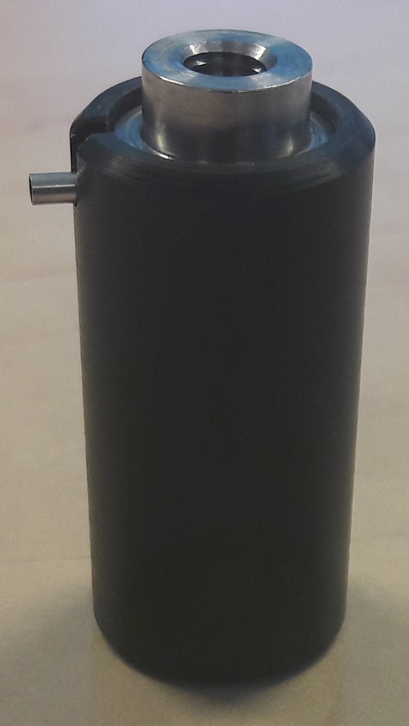
Clean waste separator
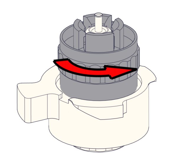
Removing
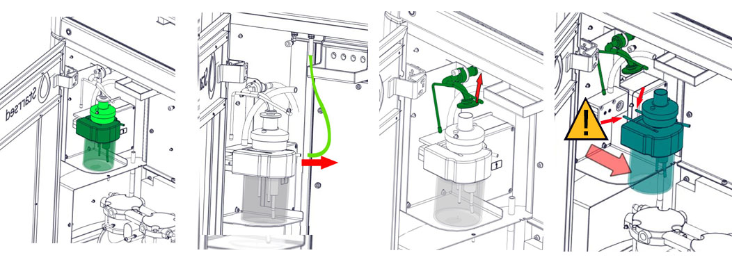
A. Clean all parts with hot water and a brush.
B. Use some acid free vaseline on the screw-thread of the glass jar, the top rim of the glass jar, the O-ring for the HEPA filter and the black PVC pipe on the back.
Cleaning
C. If applicable replace the bacterial HEPA filter (For Maintenance Level 4: Exchange filter QWLV040002)
Replacing
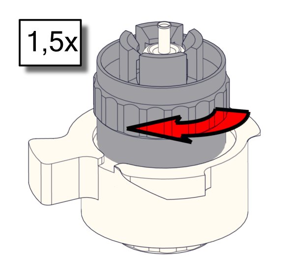
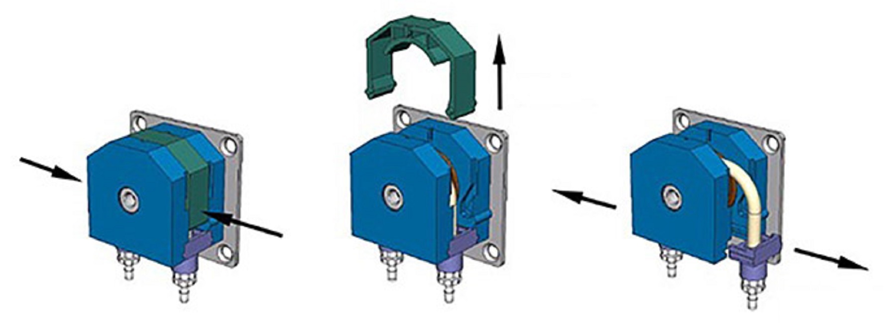
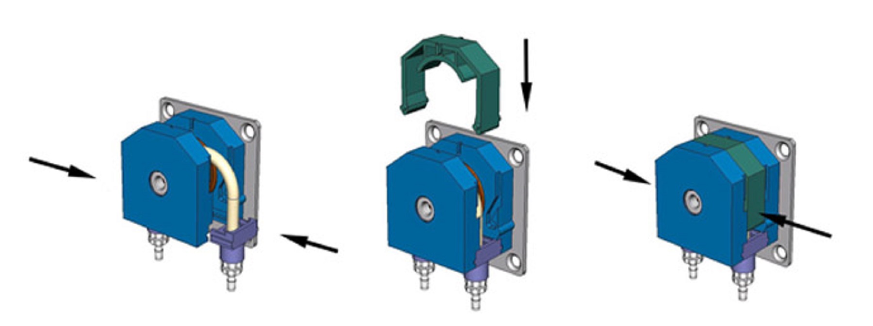
Exchange peristaltic pump tubes
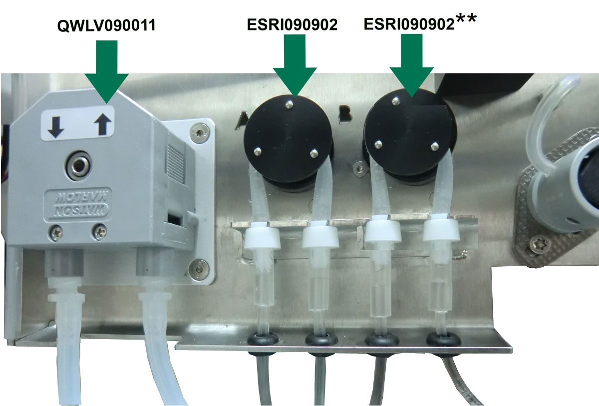
New tube replacement:
After Single needle modification A0017825: Pump A+B ESRI090902 Ø5x7 mm
**In case of original needle configuration TLAX090901: Pump A ESRI090902 Ø5x7 mm, Pump B ESRI090903 Ø2.5x4.5 mm
The pumps can be reached best by removing the plate under the carousel and open doors.
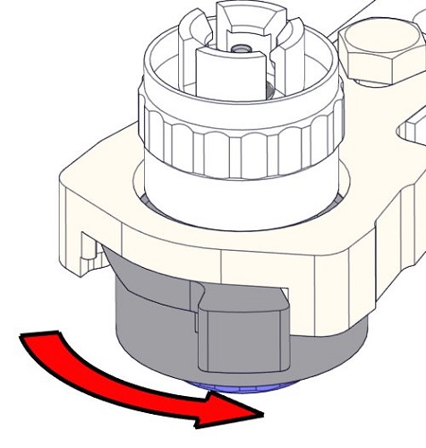
- Pull pump tube slightly downwards and at the same time towards the front of the unit to release the tube out of the pump plate holder.
- Remove the old tube from the peristaltic pump rotor.
- Disconnect the tubing at both ends of the tube connectors.
- Connect new tubing to both ends of the connectors.
- Place one end of the tube in the pump plate holder.
- Pull the new tube over the peristaltic pump rotor.
- Pull pump tube slightly downwards and at the same time towards the back of the Starrsed TL.
If the tube is not fitted correctly or is worn the following symptoms can occur:
- Liquid flowing back into the cubitainer.
- First glass tube on the pipette belt is not washed sufficiently.
Note: The wider bore tube is for the pump A.
Waste pump tube QWLV090011 in cassette.
Remove the old tube from the pump as shown:
- Pull the tube from the connectors and install the new tube in the reverse order.
- Check that all connecting tubes and the tube cover are attached.
Fill and clean
- Fill beaker with hot de-ionized water (± 130 ml, ±80°C).
- Add ±13 ml cleaning agent (QRR 010905) to the hot de-ionized water.
- Mix the solution well.
- Fill adapter TLAX110906 with the cleaning solution.
- Turn adapter upside down and remove cap (from dummy tube) and start filling the adapter until the dummy sample tube is filled without air.
- Place cap on dummy sample tube and turn adapter again, fill the adapter completely. Check for air in the dummy sample tube. - Ensure that the Starrsed TL is in Service mode, the status is also indicated with orange LED light.
- Enable "Sample Mode On"
- Ensure the needle is in "Down" position.
- Select Maintenance; Prime/Clean, Fill & Clean.
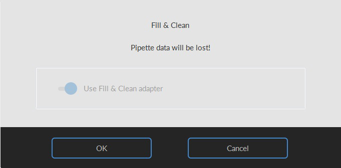
- Select button OK. Now the tube disk can be moved freely.
- Place the adapter with dummy tube on the tube disk. Ensure tubing between adapter and dummy sample tube is below the tube disk.
- Rotate the tube disk until the dummy sample tube is centered over the needle.
- Close the hood and press Continue.
- The needle goes up and the fill and clean process is started. (This cycle takes about 90 minutes).
- When all the pipettes are filled, the needle goes back to the home position.
- Remove the adapter unit.
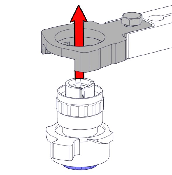
Replace needle O-ring (if applicable)
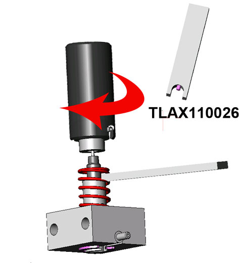
For assembling and disassembling the special needle holder tool TLAX110023 and spanner TLAX110026 are needed.
Needle removal
- Remove drip tray (metal sheet under needle unit, behind door)
- Disconnect both tubes.
- Loosen the knurled knob.
- Remove the complete needle assembly outside the instrument.
- Clean the needle with a disinfectant.
O-ring replacement
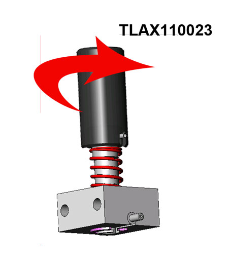
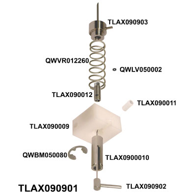
- Use the needle tool TLAX110023 to loosen the outer needle from the needle holder.
Warning: Be aware of spring tension - Store outer needle in tool TLAX110023.
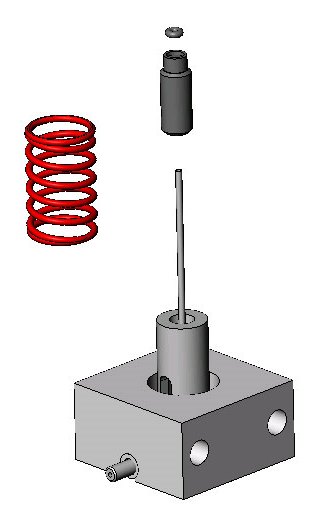
- Remove the spring QWVR0012260.
- Loosen TLAX090012 O-ringscrew from the needle holder.
- Remove the O-ring QWLV050002.
- If needed: Grease the outside of the inner needle base by removing TLAX090011 (use acid free vaseline).
- Fit a new O-ring QWLV050002 carefully, and press the O-ring into the recess.
- Place the O-ring screw over the inner needle so that the internal hexagonal hole is facing the inside of the needle holder.
- The small hole in the O-ring screw should stay about 2 mm above the holder.
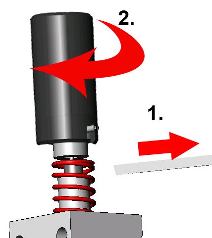
- Place the spring QWVR012260 over the inner needle, insert the special O-ring screw spanner TLAX110026, and tighten the O-ring screw slightly.
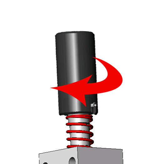
- Hold the needle assembly block tight and turn just the spring clockwise.
- Insert the outer needle carefully into the needle tool TLAX110023, place the inner needle, without damaging the inner needle tip, straight through the outer needle.
- Hold the spanner TLAX110026 in one hand, and tighten (hand-tight) the outer needle by turning the needle tool TLAX110023 clock-wise.
- Remove the spanner TLAX110026, hold the needle assembly by the assembly block, and tighten the outer needle firmly with TLAX110023.
- Check if the pipes are facing the same direction.
- Compress the needle assembly, it should move smoothly.
Check for leakage
- Check the needle assembly for leakage by short-circuiting both ends of the outer needle with a short length of tubing.
- Connect a syringe with air to the inner needle and immerse it in water.
- Pressurize it with the syringe - air bubbles should not be visible.
- Dry all parts.
Needle assembly
- Place the needle back on the instrument.
- Fasten the knurled knob, do not fasten too tight
- Connect both tubes to the needle.
- Place drip tray.
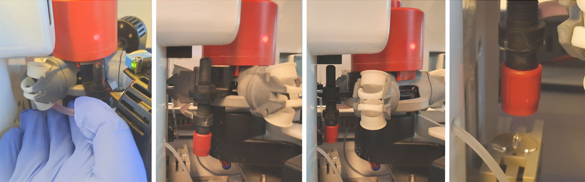
Check/Clean liquid sensor
The Liquid sensor on the Processing unit has to be checked on regular base and cleaned if necessary.
- Remove the silicone tube (in red box) from the middle slot of the Liquid sensor. Check the outside of the tube and check each slot closely to ensure no white substance or dust is blocking the LEDs. If cleaning is needed, continue with step 2.
- Clean the tube near the Liquid sensor with De-ionized water and dry with canned air or a gauze pad.
- Remove the drip tray under the needle.
- Use a (dedicated) soft fine bristle toothbrush to remove any foreign particles in front of the sensor LEDs. Brush up and down in the slots on the left and right side of the tube space (shown in red).
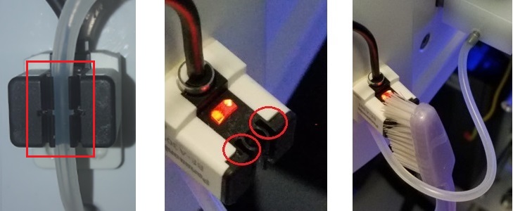
- Replace the silicone tube into middle slot of Liquid sensor and test under Maintenance - Check sensors-Check Liquid Sensor-Test. The Rinse and Drain should show two blue check marks.
Check sensors
Vacuum pressure check
- Go to tab Maintenance -> Check sensor. Select Check Flow sensor box.
Flow: 0980 ± 60 Abs: 0320 ±10
If the flow is not in range there might be a blockage in the vacuum flow line to the flow sensor.
Fill Stop sensor check
- Go to tab Maintenance -> Check sensor. Select Check Fill stop sensor box.
Fill stop sensor FS 90..140..165
Diluter Start sensor check
- Go to tab Maintenance -> Check sensor. Select Diluter start sensor box.
Diluter start sensor 400-550-700
Measure sensor check
- Go to tab Maintenance -> Check sensor. Select Check measure sensor box.
Measure sensor MS 50 ±10
Temperature sensor check
- Go to tab Maintenance -> Check sensor. Select Check Temperature sensor box.
Temperature sensor TS [Room temperature]
Diluent flow sensor check
- Go to tab Maintenance -> Check sensor. Select Check Diluent flow sensor box.
Press test. When test is finished, signal Standby and Flow must shown as activated.
Separator check
- Go to tab Maintenance -> Check sensor. Select Check Separator sensor box.
Separator sensor <200 600 >700
Liquid sensor check
- Go to tab Maintenance -> Check sensor. Select Check liquid sensor box.
Check liquid sensor: Press test. When test is finished, the OK signs are shown at Rinse and Drain if the liquid sensor is active.
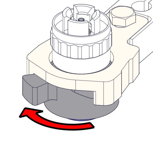
Exchange pinch valve
Replace the pinch valve tube ESRI010246.
Clean and check instrument
- Check system for leakage.
- Check drip trays under pump assembly and needle assembly.
- Open carousel plate and inspect the peristaltic pump tubes and connections for leaks.
- Check tubing from the syringe for trapped air bubbles.
- Check Diluent syringe for trapped air bubbles.
- If trapped air bubbles are found, go to tab [Maintenance], click button [Prime / Clean] and perform the [Prime Diluent] function.
- Clean needle top with disinfectant.
- Wipe stainless steel plates below the pipettes with disinfectant.
- Close cover/front doors and activate the instrument in the LAS.
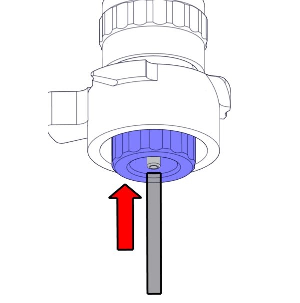
Air filter replacement
Air filter replacement QWLV040003
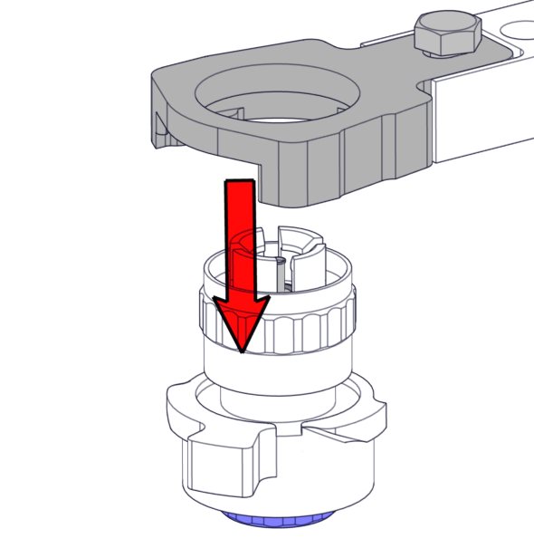
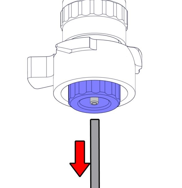
- Pull both tube connectors out of the blue disk filter.
- Place new blue disk filter
- Reconnect the tube connectors on the filter

Mechatronics home
Send Feedback
Print
|
Page last reviewed: 04/05/2022 12:13:23 (Version: 1.10 (05-09-2022) MRN-174_2-EN) ©2022 RR Mechatronics |